ShiboSoftwareDev/mspm0g3507-usb-c-dev-board
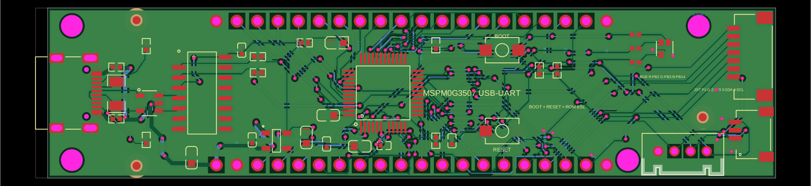
The circuit assembles a USB-C port with integrated ESD protection, power regulation, UART interface, and microcontroller (MSPM0G3507) with supporting components for USB data lines, CC termination, I2C, SPI, reset circuitry, and indicator LEDs.
- Version
- 1.4.2
- License
- unset
- Stars
- 0
outputs/README.md
PCB
Schematic

# JLCPCB release files — MSPM0G3507 USB-C board v1.4.2

These files were generated together from `index.circuit.tsx` using tscircuit 0.0.2462.

- `MSPM0G3507_USB_C_JLCPCB_Gerbers.zip`: two copper layers, masks, top and bottom paste, silkscreens, board outline, fabrication drawing, plated/NPTH drills, and the same manufacturer-rich BOM/CPL embedded in the ZIP.
- `MSPM0G3507_USB_C_JLCPCB_BOM.csv`: 38-placement BOM with JLCPCB and manufacturer part numbers.
- `MSPM0G3507_USB_C_JLCPCB_CPL.csv`: 38-placement pick-and-place list.
- `MSPM0G3507_USB_C_PCB.svg`: routed PCB preview.
- `MSPM0G3507_USB_C_Schematic.svg`: schematic preview.
- `MSPM0G3507_USB_C_Assembly.svg`: assembly drawing.

The fabrication audit confirms a uniform 90 mm × 21 mm Pico-width outline, Pico-compatible 17.78 mm header-row spacing on a 2.54 mm breadboard grid, adjacent outer breadboard-hole centers 0.93 mm beyond each edge, two copper layers, 0.30 mm drill / 0.45 mm pad top-to-bottom through-vias only, four isolated M2.5 mounting holes, four correctly oriented USB-C shield slots, 40 header holes, four Grove connector holes, all top-side SMT paste apertures, and no bottom-side paste apertures. The in-stock headers use their exact supplier land pattern: 1.6 mm round lands around 1.05 mm drills, with a 0.275 mm annular ring and 0.81 mm copper-to-edge clearance. The RGB LED uses the exact imported JLCPCB C3029072 land pattern, with the rotated physical pad order checked so pin 4 is the common cathode and pins 1/2/3 are red/green/blue. Every BOM placement has an exact manufacturer part number and JLCPCB part number; all 25 unique parts were in stock at the live 2026-09-09 check.

Upload the Gerber ZIP as the PCB file and the standalone BOM/CPL for assembly. The 1×20 headers and Grove connector are through-hole parts and may require JLCPCB through-hole assembly or hand soldering.
Related Packages
 More from this authorShiboSoftwareDev/lp-msp430fr2476This design implements a microcontroller-based development board featuring an MSP430FR2476 target MCU with associated power regulation, USB host interface with ESD protection, multiple headers for peripherals and BoosterPacks, and integrated status LEDs and sensors.
 Similar packageaura/diy-power-delivery-triggerThis hardware design implements a USB Type-C port with supporting power management and signal conditioning components, including a USB-C connector, a FUSB302 USB-C port controller, ESD protection diodes, a buck converter for 3.3V power regulation, an STM32 microcontroller for control and processing, an RGB LED indicator, push button, terminal block connections, and associated filtering and support components.
 Discover something newrushabhcodes/ESP32-E-ReaderThis code defines the physical layout and schematic wiring of an ESP32-based e-reader device, including various surface-mount components such as connectors, ICs, resistors, capacitors, inductors, diodes, pushbuttons, and an antenna, with precise PCB placement and interconnection details.