gokul/acoustic-guitar-tuner
This code defines a miniature circuit board featuring a microcontroller (ATTINY1616-MNR), audio and power components, tactile switch, various LEDs, and passive components arranged with specific footprints, connections, and mechanical markings for a mini acoustic guitar tuner.
- Version
- 1.0.8
- License
- unset
- Stars
- 2
index.circuit.tsx
PCB
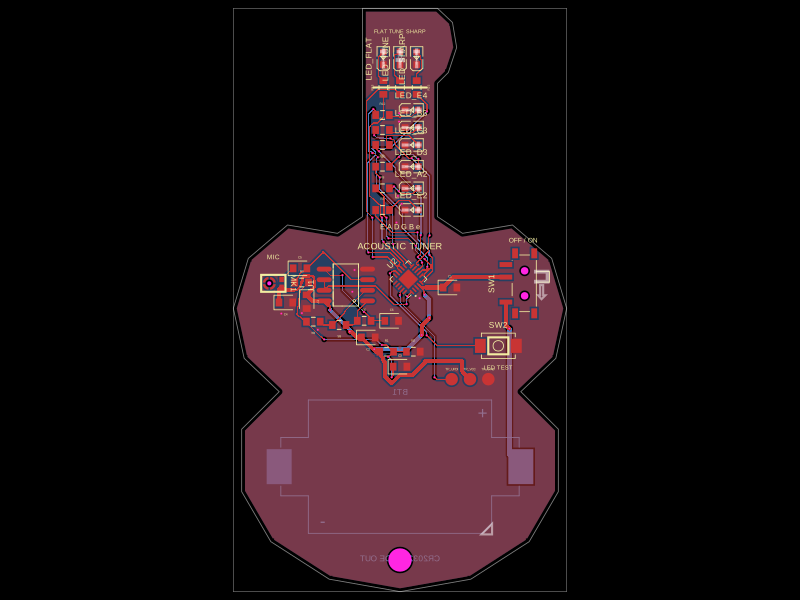
Schematic

import { ATTINY1616_MNR } from "./imports/ATTINY1616_MNR"
import { HX_3x4x2_2P_1_6N_TACTILE_SWITCH } from "./imports/HX_3x4x2_2P_1_6N_TACTILE_SWITCH"
import { MCP6002T_I_SN } from "./imports/MCP6002T_I_SN"
import { MSM381ACB026 } from "./imports/MSM381ACB026"
import { MSK12C02 } from "./imports/MSK12C02"
import { XDCR_2032_603 } from "./imports/XDCR_2032_603"
import { XL_1608SURC_06 } from "./imports/XL_1608SURC_06"
import { XL_1608SYGC_06 } from "./imports/XL_1608SYGC_06"
import { XL_1608UYC_06 } from "./imports/XL_1608UYC_06"

const guitarOutline = [
  { x: -4.5, y: 39 },
  { x: 4.5, y: 39 },
  { x: 6.3, y: 37.3 },
  { x: 6.8, y: 34.3 },
  { x: 5.8, y: 31.3 },
  { x: 4.5, y: 30 },
  { x: 4.5, y: 14 },
  { x: 7.5, y: 12 },
  { x: 13.5, y: 13 },
  { x: 18.2, y: 9 },
  { x: 20, y: 3 },
  { x: 18.7, y: -3 },
  { x: 14.5, y: -7 },
  { x: 19, y: -11.5 },
  { x: 19, y: -19 },
  { x: 15.5, y: -25 },
  { x: 8.5, y: -29.5 },
  { x: 0, y: -31 },
  { x: -8.5, y: -29.5 },
  { x: -15.5, y: -25 },
  { x: -19, y: -19 },
  { x: -19, y: -11.5 },
  { x: -14.5, y: -7 },
  { x: -18.7, y: -3 },
  { x: -20, y: 3 },
  { x: -18.2, y: 9 },
  { x: -13.5, y: 13 },
  { x: -7.5, y: 12 },
  { x: -4.5, y: 14 },
]

const resistorPart = { jlcpcb: ["C21190"] }
const resistor10kPart = { jlcpcb: ["C2906982"] }
const resistor100kPart = { jlcpcb: ["C25803"] }
const capacitor100nPart = { jlcpcb: ["C7501158"] }
const capacitor1uPart = { jlcpcb: ["C20070307"] }

export default () => (
  <board
    title="Mini Acoustic Guitar Tuner"
    outline={guitarOutline}
    layers={2}
    thickness="1.6mm"
    autorouter="auto_local"
    schAutoLayoutEnabled
    schTraceAutoLabelEnabled
  >
    <schematicsheet name="main" displayName="Mini Acoustic Guitar Tuner" sheetSize="A4">

    {/* Power: CR2032, hard power switch, rail decoupling and mid-rail bias. */}
    <XDCR_2032_603 name="BT1" layer="bottom" pcbX={0} pcbY={-16} />
    <MSK12C02 name="SW1" pcbX={14.2} pcbY={6} pcbRotation={90} schRotation={90} />
    <capacitor name="C1" capacitance="100nF" footprint="0603" supplierPartNumbers={capacitor100nPart} pcbX={6} pcbY={5.5} schOrientation="vertical" />
    <capacitor name="C2" capacitance="1uF" footprint="0603" supplierPartNumbers={capacitor1uPart} pcbX={-3.8} pcbY={-0.5} schOrientation="vertical" />
    <resistor name="R1" resistance="100k" footprint="0603" supplierPartNumbers={resistor100kPart} pcbX={-1.6} pcbY={-2.2} schOrientation="vertical" />
    <resistor name="R2" resistance="100k" footprint="0603" supplierPartNumbers={resistor100kPart} pcbX={1.6} pcbY={-2.2} schOrientation="vertical" />
    <capacitor name="C3" capacitance="1uF" footprint="0603" supplierPartNumbers={capacitor1uPart} pcbX={0} pcbY={-4} schOrientation="vertical" />
    <capacitor name="C7" capacitance="100nF" footprint="0603" supplierPartNumbers={capacitor100nPart} pcbX={-11.2} pcbY={3.8} pcbRotation={270} schOrientation="vertical" />

    {/* Audio: bottom-port microphone, AC coupling, x11 gain and 1.6 kHz low pass. */}
    <MSM381ACB026 name="MK1" pcbX={-15.2} pcbY={6} pcbRotation={270} schWidth={1.7} schHeight={0.4} schPinArrangement={{ leftSide: { pins: ["VDD", "GND"], direction: "top-to-bottom" }, rightSide: { pins: ["OUT"], direction: "top-to-bottom" } }} />
    <capacitor name="C4" capacitance="100nF" footprint="0603" supplierPartNumbers={capacitor100nPart} pcbX={-13.7} pcbY={3.7} schOrientation="vertical" />
    <capacitor name="C5" capacitance="100nF" footprint="0603" supplierPartNumbers={capacitor100nPart} pcbX={-12} pcbY={7.8} schOrientation="vertical" />
    <resistor name="R3" resistance="100k" footprint="0603" supplierPartNumbers={resistor100kPart} pcbX={-11.8} pcbY={6.1} schOrientation="vertical" />
    <MCP6002T_I_SN
      name="U1"
      pcbX={-6.5}
      pcbY={5.8}
      pcbRotation={90}
      schWidth={2.5}
      schHeight={1}
      schPinArrangement={{
        leftSide: { pins: ["INA_POS", "INA_NEG", "INB_POS", "INB_NEG"], direction: "top-to-bottom" },
        rightSide: { pins: ["VDD", "OUTA", "OUTB", "VSS_NEG"], direction: "top-to-bottom" },
      }}
    />
    <resistor name="R4" resistance="10k" footprint="0603" supplierPartNumbers={resistor10kPart} pcbX={-10.4} pcbY={1.4} pcbRotation={180} schOrientation="vertical" />
    <resistor name="R5" resistance="100k" footprint="0603" supplierPartNumbers={resistor100kPart} pcbX={-7.3} pcbY={1} pcbRotation={180} />
    <resistor name="R6" resistance="10k" footprint="0603" supplierPartNumbers={resistor10kPart} pcbX={-4.3} pcbY={1.5} />
    <capacitor name="C6" capacitance="10nF" footprint="0603" pcbX={-1} pcbY={1.5} schOrientation="vertical" />

    {/* Control: ADC sampling, one mode button and UPDI test pads. */}
    <ATTINY1616_MNR
      name="U2"
      pcbX={1}
      pcbY={6.5}
      pcbRotation={45}
      schWidth={2.2}
      schHeight={2.2}
      schPinArrangement={{
        leftSide: { pins: ["VDD", "PA2", "PA3", "PA4", "PA5", "PA6", "PA7", "PA1", "PA0_UPDI", "GND", "EP"], direction: "top-to-bottom" },
        rightSide: { pins: ["PB5", "PB4", "PB3", "PB2", "PB1", "PB0", "PC0", "PC1", "PC2", "PC3"], direction: "top-to-bottom" },
      }}
    />
    <HX_3x4x2_2P_1_6N_TACTILE_SWITCH name="SW2" pcbX={11.8} pcbY={-1.5} schRotation={-90} />
    <testpoint name="TP_UPDI" footprintVariant="pad" padShape="circle" padDiameter="1.5mm" pcbX={6.2} pcbY={-5.5} />
    <testpoint name="TP_VCC" footprintVariant="pad" padShape="circle" padDiameter="1.5mm" pcbX={8.4} pcbY={-5.5} />
    <testpoint name="TP_GND" footprintVariant="pad" padShape="circle" padDiameter="1.5mm" pcbX={10.6} pcbY={-5.5} />

    {/* Six standard-string indicators along the neck: E2 A2 D3 G3 B3 E4. */}
    <resistor name="R7" resistance="1k" footprint="0603" supplierPartNumbers={resistorPart} pcbX={-2.1} pcbY={14.8} schOrientation="vertical" />
    <XL_1608UYC_06 name="LED_E2" color="yellow" pcbX={1.4} pcbY={14.8} schRotation={90} />
    <resistor name="R8" resistance="1k" footprint="0603" supplierPartNumbers={resistorPart} pcbX={-2.1} pcbY={17.4} schOrientation="vertical" />
    <XL_1608UYC_06 name="LED_A2" color="yellow" pcbX={1.4} pcbY={17.4} schRotation={90} />
    <resistor name="R9" resistance="1k" footprint="0603" supplierPartNumbers={resistorPart} pcbX={-2.1} pcbY={20} schOrientation="vertical" />
    <XL_1608UYC_06 name="LED_D3" color="yellow" pcbX={1.4} pcbY={20} schRotation={90} />
    <resistor name="R10" resistance="1k" footprint="0603" supplierPartNumbers={resistorPart} pcbX={-2.1} pcbY={22.6} schOrientation="vertical" />
    <XL_1608UYC_06 name="LED_G3" color="yellow" pcbX={1.4} pcbY={22.6} schRotation={90} />
    <resistor name="R11" resistance="1k" footprint="0603" supplierPartNumbers={resistorPart} pcbX={-2.1} pcbY={24.4} schOrientation="vertical" />
    <XL_1608UYC_06 name="LED_B3" color="yellow" pcbX={1.4} pcbY={24.7} schRotation={90} />
    <resistor name="R12" resistance="1k" footprint="0603" supplierPartNumbers={resistorPart} pcbX={-2.1} pcbY={26.2} schOrientation="vertical" />
    <XL_1608UYC_06 name="LED_E4" color="yellow" pcbX={1.4} pcbY={26.8} schRotation={90} />

    {/* Headstock tuning direction indicators. */}
    <resistor name="R13" resistance="1k" footprint="0603" supplierPartNumbers={resistorPart} pcbX={-2} pcbY={29.5} pcbRotation={90} schOrientation="vertical" />
    <XL_1608SURC_06 name="LED_FLAT" color="red" pcbX={-2} pcbY={33} pcbRotation={90} schRotation={90} />
    <resistor name="R14" resistance="1k" footprint="0603" supplierPartNumbers={resistorPart} pcbX={0} pcbY={29.5} pcbRotation={90} schOrientation="vertical" />
    <XL_1608SYGC_06 name="LED_TUNE" color="green" pcbX={0} pcbY={33} pcbRotation={90} schRotation={90} />
    <resistor name="R15" resistance="1k" footprint="0603" supplierPartNumbers={resistorPart} pcbX={2} pcbY={29.5} pcbRotation={90} schOrientation="vertical" />
    <XL_1608SURC_06 name="LED_SHARP" color="red" pcbX={2} pcbY={33} pcbRotation={90} schRotation={90} />

    {/* Mechanical and user-facing markings. */}
    <hole name="H1" diameter="2.8mm" pcbX={0} pcbY={-27.2} />
    <silkscreentext text="ACOUSTIC TUNER" fontSize="1.1mm" pcbX={0} pcbY={10.5} anchorAlignment="center" />
    <silkscreentext text="E  A  D  G  B  e" fontSize="0.9mm" pcbX={0} pcbY={12.8} anchorAlignment="center" />
    <silkscreentext text="FLAT   TUNE   SHARP" fontSize="0.65mm" pcbX={0} pcbY={36.2} anchorAlignment="center" />
    <silkscreentext text="MIC" fontSize="0.8mm" pcbX={-15.2} pcbY={9.2} anchorAlignment="center" />
    <silkscreentext text="LED TEST" fontSize="0.7mm" pcbX={11.8} pcbY={-4.1} anchorAlignment="center" />
    <silkscreentext text="OFF / ON" fontSize="0.8mm" pcbX={14.8} pcbY={11.2} anchorAlignment="center" />
    <silkscreentext text="CR2032 + SIDE OUT" fontSize="1mm" layer="bottom" pcbX={0} pcbY={-27} anchorAlignment="center" />
    <silkscreenpath route={[{ x: -3.2, y: 29.5 }, { x: 3.2, y: 29.5 }]} strokeWidth="0.25mm" />

    {/* Power and reference nets. */}
    <trace from="BT1.pin1" to="SW1.pin1" width="0.5mm" />
    <trace from="BT1.pin2" to="net.GND" width="0.5mm" />
    <trace from="SW1.pin2" to="net.VCC" width="0.5mm" />
    <trace from="C1.pin1" to="net.VCC" /><trace from="C1.pin2" to="net.GND" />
    <trace from="C2.pin1" to="net.VCC" /><trace from="C2.pin2" to="net.GND" />
    <trace from="R1.pin1" to="net.VCC" /><trace from="R1.pin2" to="net.VREF" />
    <trace from="R2.pin1" to="net.VREF" /><trace from="R2.pin2" to="net.GND" />
    <trace from="C3.pin1" to="net.VREF" /><trace from="C3.pin2" to="net.GND" />
    <trace from="C7.pin1" to="net.VCC" /><trace from="C7.pin2" to="net.GND" />

    {/* Microphone and analog signal chain. */}
    <trace from="MK1.VDD" to="net.VCC" /><trace from="MK1.pin3" to="net.GND" />
    <trace from="C4.pin1" to="net.VCC" /><trace from="C4.pin2" to="net.GND" />
    <trace from="MK1.OUT" to="C5.pin1" /><trace from="C5.pin2" to="net.MIC_AC" />
    <trace from="R3.pin1" to="net.MIC_AC" /><trace from="R3.pin2" to="net.VREF" />
    <trace from="U1.INA_POS" to="net.MIC_AC" /><trace from="U1.INA_NEG" to="net.FB_A" />
    <trace from="R4.pin1" to="net.FB_A" /><trace from="R4.pin2" to="net.VREF" />
    <trace from="U1.OUTA" to="net.PREAMP" /><trace from="R5.pin1" to="net.PREAMP" /><trace from="R5.pin2" to="net.FB_A" />
    <trace from="R6.pin1" to="net.PREAMP" /><trace from="R6.pin2" to="net.FILTER" />
    <trace from="C6.pin1" to="net.FILTER" /><trace from="C6.pin2" to="net.GND" />
    <trace from="U1.INB_POS" to="net.FILTER" /><trace from="U1.INB_NEG" to="net.AUDIO_ADC" /><trace from="U1.OUTB" to="net.AUDIO_ADC" />
    <trace from="U1.VDD" to="net.VCC" /><trace from="U1.VSS_NEG" to="net.GND" />

    {/* MCU power, ADC, button and programming. */}
    <trace from="U2.VDD" to="net.VCC" /><trace from="U2.GND" to="net.GND" /><trace from="U2.EP" to="net.GND" />
    <trace from="U2.PA2" to="net.AUDIO_ADC" />
    <trace from="U2.PB0" to="SW2.pin1" /><trace from="SW2.pin2" to="net.GND" />
    <trace from="U2.PA0_UPDI" to="TP_UPDI.pin1" /><trace from="TP_VCC.pin1" to="net.VCC" /><trace from="TP_GND.pin1" to="net.GND" />

    {/* LED drive outputs; firmware lights only the selected string/status LEDs. */}
    <trace from="U2.PA4" to="R7.pin1" /><trace from="R7.pin2" to="LED_E2.pos" /><trace from="LED_E2.neg" to="net.GND" />
    <trace from="U2.PA5" to="R8.pin1" /><trace from="R8.pin2" to="LED_A2.pos" /><trace from="LED_A2.neg" to="net.GND" />
    <trace from="U2.PA6" to="R9.pin1" /><trace from="R9.pin2" to="LED_D3.pos" /><trace from="LED_D3.neg" to="net.GND" />
    <trace from="U2.PA7" to="R10.pin1" /><trace from="R10.pin2" to="LED_G3.pos" /><trace from="LED_G3.neg" to="net.GND" />
    <trace from="U2.PB5" to="R11.pin1" /><trace from="R11.pin2" to="LED_B3.pos" /><trace from="LED_B3.neg" to="net.GND" />
    <trace from="U2.PB4" to="R12.pin1" /><trace from="R12.pin2" to="LED_E4.pos" /><trace from="LED_E4.neg" to="net.GND" />
    <trace from="U2.PB3" to="R13.pin1" /><trace from="R13.pin2" to="LED_FLAT.pos" /><trace from="LED_FLAT.neg" to="net.GND" />
    <trace from="U2.PB1" to="R14.pin1" /><trace from="R14.pin2" to="LED_TUNE.pos" /><trace from="LED_TUNE.neg" to="net.GND" />
    <trace from="U2.PB2" to="R15.pin1" /><trace from="R15.pin2" to="LED_SHARP.pos" /><trace from="LED_SHARP.neg" to="net.GND" />

    <copperpour name="GND_TOP" connectsTo="net.GND" layer="top" clearance="0.2mm" boardEdgeMargin="0.4mm" />
    <copperpour name="GND_BOTTOM" connectsTo="net.GND" layer="bottom" clearance="0.2mm" boardEdgeMargin="0.4mm" />
    </schematicsheet>
  </board>
)
Related Packages
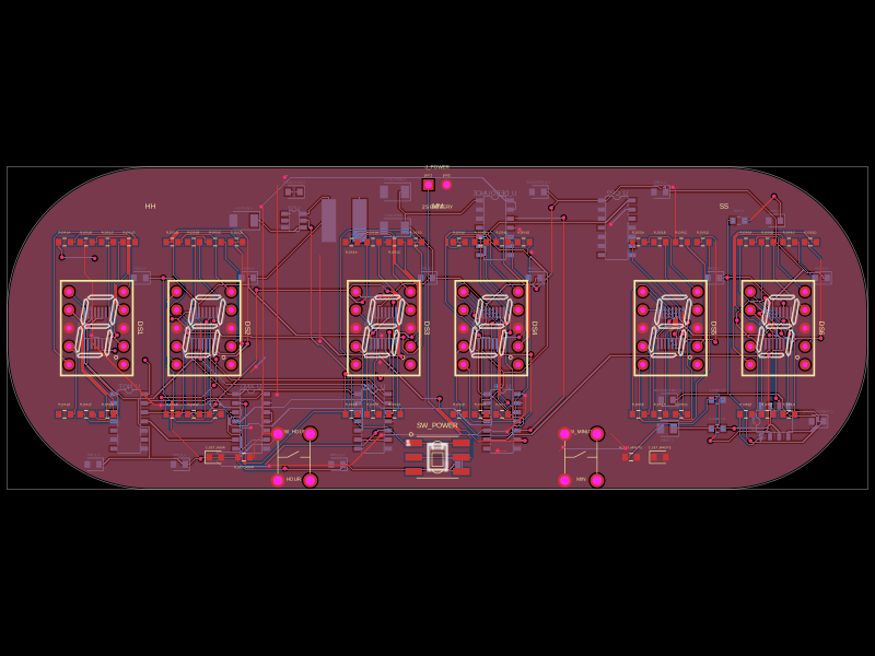 More from this authorgokul/new-clockThis code defines a PCB schematic with physical hardware components including switches, chips, resistors, capacitors, inductors, connectors, and visual annotations for a six-digit 12-hour digital clock circuit.
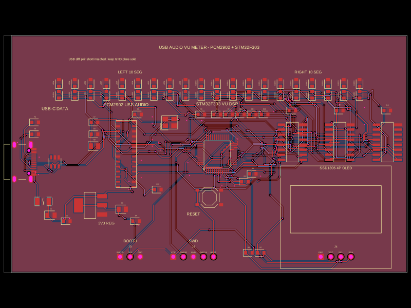 Similar packageimrishabh18/STM32F746G-DISCOThis code defines the hardware layout of a USB audio vu-meter circuit, including key components such as voltage regulators, microcontroller (STM32F303CCT6), audio codec (PCM2902), USB-Ethernet isolator, power regulation, reset switches, and associated passive components, with their physical footprints, pin configurations, and routing for PCB design.
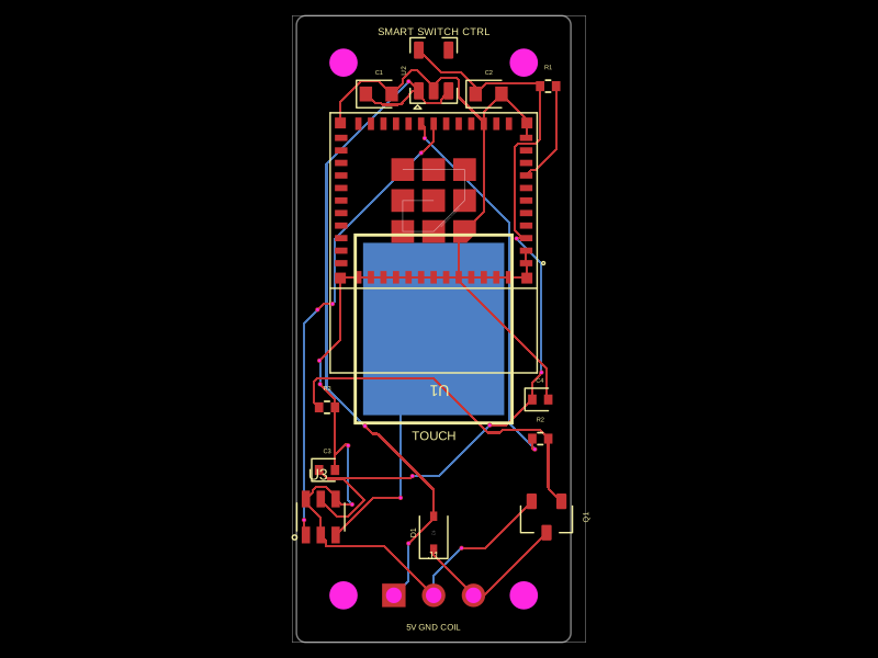 Discover something newhrithik18k/smart-switch-pcbThe AO3400A component models a SOT-23 N-channel MOSFET with labeled pins for Gate, Source, and Drain, including 3D CAD models and schematic symbols for electronic circuit design.