krishnax12/watchy-eink-smartwatch
This code defines a hardware schematic and PCB layout for a smartwatch using components like ESP32 microcontroller, sensors, Bluetooth module, power regulation, and connectors, with detailed component footprints and PCB outlines.
- Version
- 1.2.1
- License
- unset
- Stars
- 2
imports/BatteryConnector.tsx
import type { ChipProps } from "tscircuit";
import battStep from "../assets/BatteryConnector.step";

const pinLabels = {
  "pin3": ["pin3", "shield1"],
  "pin4": ["pin4", "shield2"],
  "pin1": [
    "pin1",
    "1"
  ],
  "pin2": [
    "pin2",
    "2"
  ]
} as const;

export const BatteryConnector = (props: ChipProps<typeof pinLabels>) => {
  return (
    <chip
      pinLabels={pinLabels}
      footprint={
        <footprint>
          <smtpad portHints={["pin3", "shield1"]} pcbX="3.166mm" pcbY="-1.1mm" width="2.1mm" height="2.9mm" shape="rect" />
          <smtpad portHints={["pin4", "shield2"]} pcbX="-3.166mm" pcbY="-1.1mm" width="2.1mm" height="2.9mm" shape="rect" />
          <smtpad portHints={["pin1", "1"]} pcbX="0.634mm" pcbY="1.75mm" width="0.5mm" height="1.6mm" shape="rect" />
          <smtpad portHints={["pin2", "2"]} pcbX="-0.616mm" pcbY="1.75mm" width="0.5mm" height="1.6mm" shape="rect" />
        </footprint>
      }
      cadModel={{ stepUrl: battStep, positionOffset: { x: 0, y: -2.5, z: 0 } }}
      {...props}
    />
  );
};
Related Packages
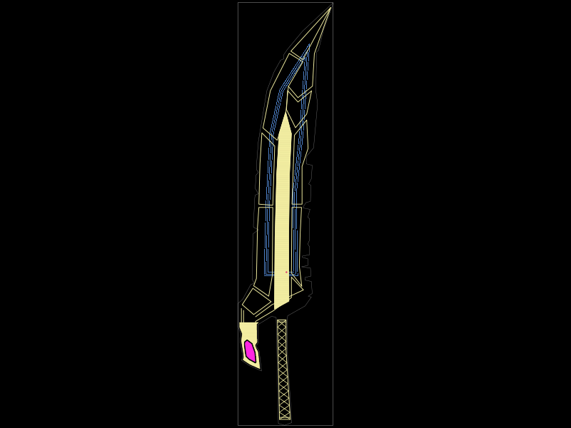 More from this authorkrishnax12/tensa-zangetsu-keychain-nfcThis code defines a PCB footprint and 3D model for an NFC-enabled electronic component featuring an NXP NT2H1311F0DTLH chip, a PCB copper coil antenna, and a custom-shaped, silkscreen-illustrated metal blade housing.
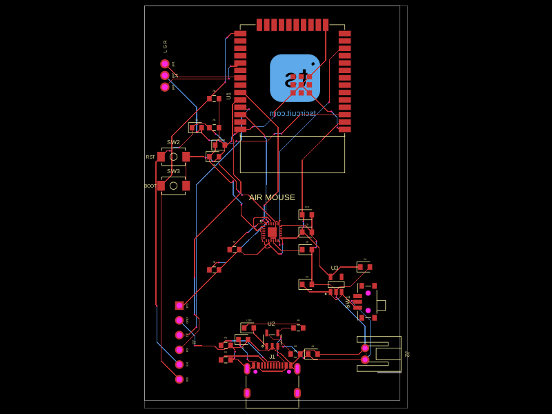 Similar packagehrithik18k/air-mouseThis code defines various surface-mount and through-hole electronic components, specifying their physical footprints, pin configurations, and 3D CAD models for hardware visualization.
 Discover something newrushabhcodes/ESP32-E-ReaderThis code defines the physical layout and schematic wiring of an ESP32-based e-reader device, including various surface-mount components such as connectors, ICs, resistors, capacitors, inductors, diodes, pushbuttons, and an antenna, with precise PCB placement and interconnection details.