techmannih/trellis-core
This code defines a detailed electronic hardware schematic and PCB layout for a Linux System-on-Module, incorporating components such as oscillators, power regulators, USB-C connectors, connectors, LEDs, resistors, capacitors, inductors, and integrated circuits, with precise physical footprint and 3D models.
- Version
- 0.2.13
- License
- unset
- Stars
- 0
imports/Q13FC13500004.tsx
import type { ChipProps } from "@tscircuit/props"

const pinLabels = {
  pin1: ["pin1"],
  pin2: ["pin2"]
} as const

export const Q13FC13500004 = (props: ChipProps<typeof pinLabels>) => {
  return (
    <chip
      pinLabels={pinLabels}
      symbol={
        <symbol>
          <port
            name="pin1"
            pinNumber={1}
            aliases={["1"]}
            direction="left"
            schX={-0.8}
            schY={0}
            schStemLength={0.3}
          />
          <port
            name="pin2"
            pinNumber={2}
            aliases={["2"]}
            direction="right"
            schX={0.8}
            schY={0}
            schStemLength={0.3}
          />
          <schematicpath
            points={[
              { x: -0.22, y: -0.32 },
              { x: -0.22, y: 0.32 },
            ]}
            strokeWidth={0.02}
            strokeColor="#8D2323"
          />
          <schematicrect
            schX={0}
            schY={0}
            width={0.2}
            height={0.56}
            strokeWidth={0.02}
            color="#880000"
          />
          <schematicpath
            points={[
              { x: 0.22, y: -0.32 },
              { x: 0.22, y: 0.32 },
            ]}
            strokeWidth={0.02}
            strokeColor="#8D2323"
          />
          <schematicpath
            points={[
              { x: -0.5, y: 0 },
              { x: -0.22, y: 0 },
            ]}
            strokeWidth={0.02}
            strokeColor="#8D2323"
          />
          <schematicpath
            points={[
              { x: 0.22, y: 0 },
              { x: 0.5, y: 0 },
            ]}
            strokeWidth={0.02}
            strokeColor="#8D2323"
          />
          <schematictext
            text="{REF}"
            schX={0}
            schY={0.5}
            fontSize={0.2}
            anchor="center"
          />
          <schematictext
            text="32.768kHz"
            schX={0}
            schY={-0.5}
            fontSize={0.2}
            anchor="center"
          />
        </symbol>
      }
      supplierPartNumbers={{
        "jlcpcb": [
          "C32346"
        ]
      }}
      manufacturerPartNumber="Q13FC13500004"
      footprint={<footprint>
        <smtpad portHints={["pin1"]} pcbX="-1.250061mm" pcbY="0mm" width="0.999998mm" height="1.7999964mm" shape="rect" />
        <smtpad portHints={["pin2"]} pcbX="1.250061mm" pcbY="0mm" width="0.999998mm" height="1.7999964mm" shape="rect" />
        <silkscreenpath route={[{ "x": -0.5079999999999956, "y": 0.7621269999999924 }, { "x": 0.5079999999999956, "y": 0.7621269999999924 }]} />
        <silkscreenpath route={[{ "x": 0.5079999999999956, "y": -0.7618730000000085 }, { "x": -0.5079999999999956, "y": -0.7618730000000085 }]} />
        <silkscreentext text="{NAME}" pcbX="-0.012065mm" pcbY="1.91186mm" anchorAlignment="center" fontSize="1mm" />
        <courtyardoutline outline={[{ "x": -2.027365000000003, "y": 1.1618600000000043 }, { "x": 2.0032349999999894, "y": 1.1618600000000043 }, { "x": 2.0032349999999894, "y": -1.1669399999999968 }, { "x": -2.027365000000003, "y": -1.1669399999999968 }, { "x": -2.027365000000003, "y": 1.1618600000000043 }]} />
      </footprint>}
      cadModel={{
        objUrl: "https://modelcdn.tscircuit.com/easyeda_models/assets/C32346.obj?uuid=fd4574cdfbe94d00a9458103bda2310c",
        stepUrl: "https://modelcdn.tscircuit.com/easyeda_models/assets/C32346.step?uuid=fd4574cdfbe94d00a9458103bda2310c",
        pcbRotationOffset: 0,
        modelOriginPosition: { x: 0, y: -0.0001396999999911941, z: 0 },
      }}
      {...props}
    />
  )
}
Related Packages
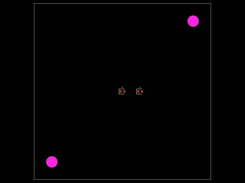 More from this authortechmannih/duplicate-NPTHA 50mm x 50mm PCB layout featuring two mounting holes, a 10kΩ resistor, and a 100nF capacitor positioned at specific coordinates.
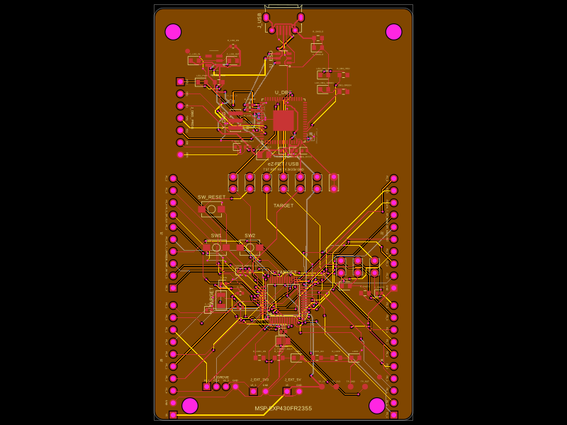 Similar packageShiboSoftwareDev/msp-exp430fr2355This code defines React components representing various surface-mount and through-hole electronic components—such as resonators, microcontrollers, crystals, connectors, and push buttons—with detailed physical footprints, 3D models, and pin configurations for PCB design.